Deliverable D7.2: Dissemination Plan (pdf)
Deliverable D1.3: Validation Plan report (pdf)
Deliverable D2.3: 1st set of prototypes (pdf)
Deliverable D7.5: Collection of Cluster newsletters/Common dissemination activities (pdf)
MILESTONES ACHIEVED
M1: The specifications and requirements for the battery thermal management system (BTMS) have been finalised and handed to WP2 and WP3 leaders (Nov 2019)
M2: Design Freeze of BTM system components completed and validated (Jan 2021)
M3: Prototypes for 1st system testing in WP 3 ready (Oct 2021)
M4: Final prototypes for demonstration ready (March 2022)
M5: Design, characterization and modelling of the BTMS completed, validated and handed over to WP4 leaders (April 2022)
M6: The BTM system has been fully assembled, commissioned, test benched and implemented (April 2023)
MAIN OUTCOMES
WP1: Requirements & Specifications
The requirements and specifications at vehicle level have been identified in terms of vehicle performances (max power, max speed, etc.) and driving range, considering the target to remain inside an interval of 60min – 90min more with respect to the driving time of an equivalent vehicle with internal combustion engine for long duration trips of 700-1000 km. Starting from such vehicle requirements, detailed specifications for the battery system have been defined in terms of volume, weight, energy, charging rate, charging power and lifetime of the pack. The battery cells have been selected after an accurate comparison of different parameters of available cells. The battery pack configuration will be composed of 12 modules, each with 15P3S cells, for a total of 540 cells. A concept for the design of the battery cooling system incorporating advanced thermal technologies has been prepared and the final implementation is discussed.
Finally, a concept and validation plan has been identified, with all the necessary virtual simulations and tests to be performed for components, systems and vehicle.
WP2: Component development, testing & modelling
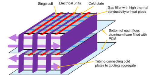
Multi-functional sandwich battery housing.An important part of the SELFIE project is the design and engineering of a battery housing which besides of mechanically supporting the battery cells provides heat storage, heating and cooling capability. The principle design of the battery housing has been successfully established; it will mainly be made of a sandwich structure consisting of glass-fibre reinforced polymer face sheets and a polymer foam core. The battery cells will be arranged on PCM loaded aluminium foam plates to buffer the heat generated during fast charge cycles in order to avoid an energy consuming high power cooling system. Furthermore, cooling plates between the battery rows and in thermal contact with the aluminium foam/PCM plates will remove the heat from the battery pack.
Battery housing structure
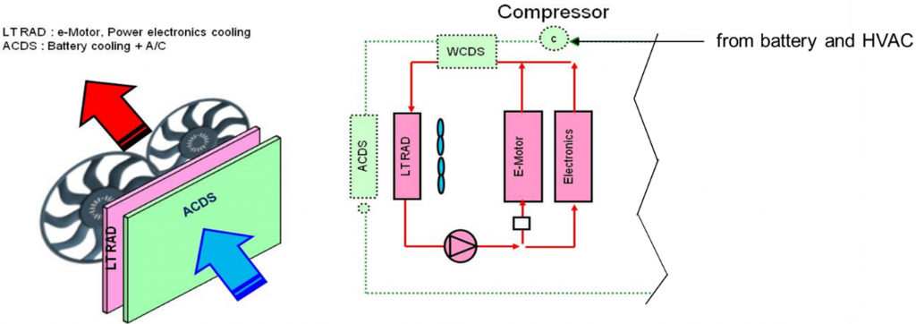
Battery Thermal management (BTM) system:For the components belonging to the thermal system architecture, the design has been finalized. To achieve enhanced cooling by the front-end module a new cooling architecture was developed, where during fast charge the refrigerant is pre-cooled by a water-cooled condenser (WCDS) in the motor/electronics loop. This loop is not active during a fast charge. This design is cost-efficient and robust compared to an earlier considered split-air approach with two air condensers (ACDS). You can find more information in the Report “1st set of prototypes” (D3.2)